

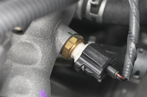
Weird cold starts, rich trims, or a radiator fan that wakes the street at dawn? A biased Engine Coolant Temperature (ECT) sensor can trick the ECU into the wrong strategy. This practical guide shows how to prove it with data, replace the sensor cleanly, and verify the fix—no parts darts.
Why ECT matters beyond the dash gauge
ECT is a master signal for warm‑up enrichment, idle speed, fan control, purge timing, transmission shift maps and even spark on some platforms. If it reads colder than reality, the ECU fattens fuel and idles high; if it reads too hot, the fan logic goes rogue and drivability suffers.
Patterns that point to a biased sensor
- Cold start stumble yet normal compression and spark. Idle hangs longer than it should.
- Fan runs cold with a stone‑cold engine or after an overnight soak.
- Fuel trims drift positive after warm‑up; rich smell on cold mornings.
- DTCs P0115–P0119 or mismatch vs ambient on scan data.
Tools you actually need
- OBD‑II scan tool with live data graphing (ECT, IAT, fuel trims, fan command)
- IR thermometer or contact probe at the thermostat housing
- Basic hand tools, catch pan, new sealing washer/O‑ring where applicable
Data‑driven diagnosis (5 quick checks)
- Ambient match: key‑on, cold engine—ECT should be within ~3–5 °C of ambient/IAT. Big offset = bias.
- Warm‑up curve: graph ECT vs time from cold to operating temp. A flat spot or step jumps suggest wiring/connector issues.
- Cross‑check IR: at operating temp, IR reading at the housing should track ECT within ~8–10 °C.
- Wiggle test: gently move the harness/connector while watching live data for spikes.
- Fan logic: if the fan kicks in while IR says 40–50 °C, the signal is lying or shorted.
Common root causes
- Internal drift of an aging NTC sensor (reads colder than reality)
- High resistance at the connector pins from coolant wicking or corrosion
- Chafed harness pulling the signal toward 0 V or 5 V
Replacement—clean, quick, no mess
- Cool engine; relieve pressure. Disconnect the battery if the OEM procedure requires.
- Unplug the connector; inspect pins for green crust. Repair if needed.
- Crack the sensor loose with a deep socket. Have a rag ready; swap quickly to reduce coolant loss.
- Install the new sensor with the correct washer/O‑ring; torque to spec—do not over‑tighten in aluminum.
- Top up coolant; perform the OEM bleed procedure to purge air.
Validation—prove the fix
- Cold ambient match restored; warm‑up curve looks smooth with no dropouts.
- Fan logic behaves; trims settle within ±5–8% after a full drive cycle.
- No weeps at the sensor after the first heat soak; re‑check level next morning.
Case study (5‑minute win)
Truck with P0171/P0174 at idle; trims normalized at 2,500 RPM. Cold ECT read 0 °C while ambient was 12 °C. Connector had green residue; new pigtail + sensor fixed the bias, fan behavior, and trims—no MAF or vacuum leaks chased.
FAQs
- Can a thermostat cause the same symptoms? Yes—verify thermostat temp with IR; if ECT matches coolant but warm‑up is abnormally slow, suspect the thermostat.
- Do I need to clear adaptations? Clear DTCs; most ECUs relearn quickly once the signal is sane.
Tip: log a baseline after the fix—ECT/IAT at cold start and trims at idle/cruise. It’s your future reference if the issue returns.