

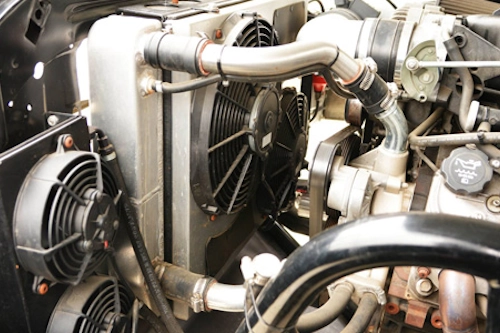
Electric cooling fans and temperature sensors are critical parts of your vehicle's thermal management system. When they fail, engines can overheat, cabin comfort suffers, and long-term engine damage becomes a real risk. This guide explains how to diagnose the cooling-fan circuit and temperature-sensing components, what tests to run with a multimeter and scan tool, how to isolate wiring or control-module faults, and what common repairs are practical for DIYers and professional mechanics alike.
Who this guide is for
- Car owners who need to understand why a car overheats or why the fan doesn't run.
- DIY mechanics who want a structured diagnostic workflow.
- Professional technicians who need a clear checklist for fan-system troubleshooting.
Tools & supplies
- Digital multimeter (volts, continuity, resistance)
- 12V auxiliary power source or jumper leads
- OBD-II scan tool (with live-data ability preferred)
- Amp clamp (optional but extremely useful)
- Screwdrivers, pliers, wrench set
- Electrical contact cleaner and dielectric grease
- Replacement fuses, relay, temperature sensor or fan motor (as needed)
- Service manual or wiring diagram for your specific vehicle
Safety first
Always disconnect the battery when making permanent wiring repairs. When testing fans, be careful of spinning blades — tie back loose clothing and avoid touching the fan. Use insulated tools near live circuits. If the engine must run during tests, secure the car on level ground with the parking brake set.
Overview of the system
Most modern vehicles use one or more electric radiator fans controlled by a fan-control module or by the engine control module (ECM). The control logic is typically based on a coolant temperature sensor (CTS), a dedicated thermoswitch, or a combination of sensor readings and AC system demand. A typical circuit includes:
- Power feed (battery via fuse and relay)
- Fan motor(s)
- Ground connection(s)
- Fan relay and possibly a fan control module
- Temperature sensor(s) and/or thermoswitch that signal the ECU
- Wiring harness and connectors
Step-by-step HowTo: Diagnose the cooling-fan circuit
-
Confirm symptoms and scan for codes
Record when the problem occurs (idle, high load, with AC on). Plug in an OBD-II tool and check for related trouble codes such as P0480–P0482 (fan control circuit). Note live data: coolant temp, commanded fan on, and AC switch state.
-
Visual inspection
Look for blown fuses, damaged relay sockets, corroded connectors or melted insulation. Check for obvious mechanical interference with the fan (debris, broken shroud). Repair or replace damaged connectors before electrical tests.
-
Check fuse and relay operation
With the key off, inspect the fan fuse(s). If a fuse is blown, replace it and test; but be cautious—if it blows again immediately, there is a short. Test the fan relay by swapping it with a known-good relay of the same type. Use the multimeter to confirm coil and contact continuity on the relay.
-
Test fan motor power feed and ground
Locate fan motor connector. With the ignition on and fan commanded (by warming the engine or using a jumper—see next step), measure voltage at the power pin. Expect battery voltage (11–14V). Then check continuity to ground on the ground pin; a high resistance indicates a bad ground.
-
Direct-power the fan (bench test)
Disconnect the fan connector and carefully apply 12V directly from the battery to the fan motor terminals (use short, insulated leads). The fan should spin freely and draw a steady current. If it doesn't spin or draws excessive current, the motor is failing and should be replaced.
-
Measure current draw
Using an amp clamp or inline ammeter, measure the fan current while running. Compare to the specification in the service manual. Excessive draw indicates worn brushes, internal short, or seized bearings; low or no draw indicates electrical or internal motor failure.
-
Check the control side (relay coil and ECU output)
Find the relay coil feed and the ECU control wire. With the fan commanded on (by temp or by asking the ECU via scan tool), measure for the presence of a control voltage on the relay coil (often ground-switched or positive-switched). If the relay coil isn't being signalled, the fault may be upstream (ECU, sensor input or wiring).
-
Test the temperature sensor / thermoswitch
Locate the coolant temperature sensor and/or the separate fan thermoswitch. Test resistance at various temperatures (reference the service manual table) or back-probe with the engine cold/warm. An open circuit or out-of-spec resistance means replace the sensor. If the sensor reads correctly yet the ECU doesn't command the fan, probe ECU voltage and ground at the sensor connector and examine the wiring harness for damage.
-
Simulate a fan request
To isolate whether the ECU or wiring is at fault, use a jumper to energize the relay coil (or apply 12V to the relay control pin). If the fan runs when directly commanded but not when the sensor reaches temperature, suspect the sensor or ECU logic. If the fan still does not run when relay coil is powered, the power feed or motor is the likely issue.
-
Diagnose intermittent faults
Wiggle test connectors and harness while monitoring for voltage drop or intermittent operation. Corrosion and broken strands inside wires often cause intermittent faults. Repair by cutting back to clean wire and crimping or soldering with heat-shrink and dielectric grease.
Common fault scenarios & fixes
- Blown fuse immediately after replacement: Look for short to ground—inspect harness for chafing; repair and replace fuse with correct rating.
- Fan doesn't run but gets voltage when commanded: Bad ground or motor internal fault—check ground, then bench-test fan for replacement.
- Fan runs constantly: Stuck relay, stuck thermoswitch, or ECU seeing false high temp—test and replace faulty relay or sensor; check wiring for shorted-to-ground signal.
- Fan cycles on/off rapidly: Faulty temp sensor, poor grounding, or intermittent relay—replace sensor and relay if tests fail.
- No fan command despite correct sensor reading: ECU output fault—check ECU grounds, fuses, and wiring. If all else fails, consult dealership/diagnostic center.
Repair tips & best practices
- Always use OEM or high-quality replacement sensors and relays; cheap sensors can drift quickly.
- When replacing connectors, use proper sealed automotive terminals and heat-shrink boots to prevent future corrosion.
- Label wires before disconnecting and consult wiring diagrams for pinouts to avoid incorrect reconnections.
- Keep a spare fan relay and fuse in the glove box—this saves time on roadside repairs.
- After repair, perform a thermal validation: run the engine to operating temperature and verify fan activation at the correct threshold and AC-on conditions.
When to seek professional help
If the diagnosis points to an ECU failure, complex wiring inside the harness (firewall/plugged harness bundles), or if the fan is integrated into a module with limited serviceability, it's advisable to consult a workshop with manufacturer-level diagnostics. Also, modern hybrid and electric vehicles can have high-voltage cooling circuits; these require trained technicians.
Conclusion
Electric fans and temperature sensors are straightforward to diagnose using a systematic approach: inspect, verify supply and ground, bench-test the motor, test the relay and control side, and confirm the sensor. With basic tools and the vehicle wiring diagram, many faults are repairable by a competent DIYer. Always prioritize safety and document your steps so you can easily reverse temporary test connections and confirm the system functions under normal operating conditions.
Practical section
Why does my fan run only when the AC is on?
Many vehicles allow the AC system to directly command the cooling fan for condenser cooling, independent of engine temperature. If the fan runs on AC but not at high engine temps, check the coolant temp sensor, fan-relay control from the ECU, and any secondary thermoswitches.