

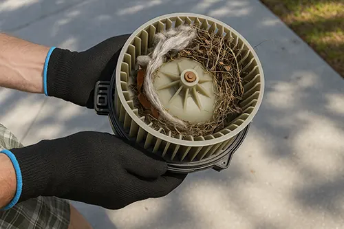
Fan speed failure matrix
The practical problem: the cabin fan doesn’t behave consistently. Sometimes it only runs on HIGH, sometimes it runs on some speeds but not others, and sometimes it cuts out after 10–15 minutes. Those patterns are useful. They let you separate a control/resistor issue from a blower motor that’s drawing too much current or has worn brushes.
Goal of this article: a repeatable test sequence that takes you from “the fan is weird” to a confident call—resistor/control, wiring/connector, or motor—without buying parts first.
- Only HIGH works: often points to resistor pack failure or a melted connector at the resistor.
- Some speeds missing: resistor pack or switch/control path.
- Cuts out on bumps: connector pin fit or harness strain.
- Runs but sounds strained: motor bearings/dragging motor can overheat the resistor over time.
Fuse relay basics first
Start boring on purpose. A blown fuse, weak relay contact, or poor ground can mimic “bad resistor.” Check the HVAC blower fuse(s) and relay seating. If you find heat-discolored fuse blades or a relay socket that smells hot, treat the socket as part of the fault.
Quick sanity check: if the blower works sometimes, don’t stop at “the fuse isn’t blown.” Intermittent contact at the fuse/relay can still be the culprit.
Resistor pack location clues
Resistor packs live in airflow so they can cool. That usually means near the blower housing under the dash. Look for a small module held by a couple of screws and a multi-pin connector. If you can see the blower motor, you’re typically one step away from the resistor or the control module.
If access is tight, take one wide photo before unplugging anything. It prevents the common “which connector went where?” reassembly mistake.
Motor current draw check
If you have a clamp meter, current draw is one of the best separators. A dragging blower motor can pull high current, overheat the resistor pack, and melt the connector—so you replace the resistor and it fails again.
- Measure on HIGH: current is usually highest there.
- Compare cold vs warm: a motor that gets worse hot is a red flag.
- No clamp meter? listen: slow start, pitch changes, or squeal suggests a motor problem.
Voltage drop under load
Voltage-drop testing under load beats guessing. Turn the blower to HIGH and measure voltage at the motor connector (or as close as you can safely access). Compare supply side vs motor side. A noticeable drop across a connector or splice indicates resistance—and resistance becomes heat.
Practical trick: gently wiggle the connector/harness while the blower runs. If the voltage drop changes or the fan cuts, you found a movement-sensitive connection problem.
Connector heat damage signs
Open the connector and inspect. You’re looking for:
- Browned or glossy plastic: heat exposure.
- Darkened terminals: arcing or high resistance.
- Loose pin fit: terminal tension loss (it feels “sloppy” when plugged in).
If the connector is heat-damaged, replacing only the resistor is a common repeat-failure path. Replace the pigtail/connector if the housing is distorted or terminals are discolored.
PWM control symptoms explained
Some systems use a resistor pack, others use an electronic blower control module (often PWM). The symptom difference can be subtle:
- Resistor style: missing low/medium speeds is common; HIGH may still work.
- Control module style: fan may surge, lag, or shut down after warm-up; control signal or module heat can be involved.
Either way, your measurement logic stays the same: confirm power/ground under load, then decide whether the control side is commanding correctly and whether the motor is drawing reasonable current.
Replacement steps done clean
- Power down the vehicle (key out/ignition off). Disconnect battery negative if access is awkward.
- Unplug the resistor/control module by releasing the latch—do not pull on wires.
- Remove mounting screws, transfer seals if applicable, and install the new unit firmly so airflow can cool it.
- If replacing a pigtail, cut back to clean copper and add strain relief so vibration cannot work-harden the splice.
Dual-unit note for common fasteners: 9 ft-lb (≈12.2 N·m), 18 ft-lb (≈24.4 N·m). Use the service manual for critical fasteners.
Post repair verification
Verification is not “it turns on.” Do this:
- All speeds test: confirm each speed or control range works.
- Heat check: run the blower 3–5 minutes and touch-check the connector area carefully (warm is normal; hot or smell is not).
- Road vibration check: a short drive can reveal a loose pin fit that the driveway test missed.
Costs time and pitfalls
- DIY time: 30–90 minutes depending on access.
- Parts: resistor/module cost varies; a connector pigtail is often cheap insurance if heat damage exists.
- Most common pitfall: replacing the resistor without addressing a high-draw blower motor or a melted connector.
If you want one rule to avoid repeat repairs: test under load, document what you measured, and fix the connector when it shows heat damage—not after the new part cooks it again.