

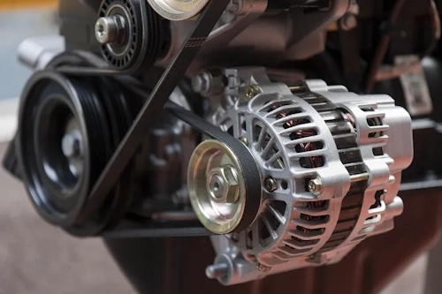
When you turn the ignition key, your vehicle awakens through a sophisticated interplay of mechanical and electrical systems. At the heart of this process lies the alternator, an electromagnetic marvel that transforms rotational energy into electrical power. This critical component charges your battery while simultaneously powering everything from headlights to infotainment systems. Unlike older DC generators, modern alternators produce alternating current (AC) that gets converted to direct current (DC) - making them significantly more efficient and reliable for automotive applications. Understanding how this complex device operates reveals the engineering genius that keeps your vehicle running smoothly mile after mile.
Core Components: Deconstructing the Alternator
Every alternator contains an intricate assembly of components working in precise harmony:
| Component | Function | Key Features |
|---|---|---|
| Rotor Assembly | Rotating electromagnet creating magnetic field | Iron core with copper field windings, slip rings, and alternating finger pole pieces |
| Stator | Stationary wire coils where electricity generates | Three-phase windings spaced 120° apart in Y-configuration |
| Rectifier Assembly | Converts AC to DC | Six silicon diodes arranged in three pairs |
| Voltage Regulator | Controls output voltage | Electronic circuit monitoring battery voltage |
| Brushes | Transmits power to rotor | Spring-loaded carbon blocks contacting slip rings |
The rotor serves as the alternator's beating heart - an electromagnet consisting of a coiled copper wire wrapped around an iron core. When voltage passes through the slip rings to this assembly, it generates a powerful magnetic field with distinct north and south poles. The rotor's clever finger pole piece design concentrates and directs this magnetic field toward the surrounding stator.
Surrounding the rotor, the stator features three sets of precisely wound copper coils arranged 120 degrees apart. This stationary component becomes the powerhouse where electricity generates through electromagnetic induction. The three-phase design ensures continuous power generation as each coil set reaches peak voltage at different points in the rotor's rotation.
Power Generation: From Rotation to Electricity
When your engine starts, it rotates the alternator's drive belt, typically at 2-3 times crankshaft speed. This spins the rotor at velocities between 6,000-12,000 RPM, creating a rotating magnetic field that sweeps past the stator windings. According to Faraday's law of electromagnetic induction, this moving magnetic field induces alternating current within the stator coils. The three-phase design produces currents that peak sequentially, ensuring continuous power output.
The alternating current generated in the stator isn't directly usable by your vehicle's electrical systems, which require direct current. This is where the rectifier assembly performs its crucial conversion:
- Six-diode configuration (three positive, three negative) creates a full-wave bridge rectifier
- Diodes act as one-way electrical valves allowing current flow in only one direction
- AC sine waves convert to pulsating DC output
- Heat sink design dissipates thermal energy from diode operation
This rectification process transforms the three-phase AC into DC suitable for battery charging and electrical system operation.
Voltage Regulation: Precision Control System
Since alternator output increases with rotational speed, an uncontrolled system could deliver up to 250 volts at highway speeds - enough to destroy your vehicle's electrical components. The voltage regulator prevents this catastrophe by constantly monitoring battery voltage and adjusting rotor field current accordingly. This sophisticated control loop maintains system voltage between 13.5-14.8 volts regardless of engine speed or electrical load.
| Condition | Regulator Response | Field Current Action |
|---|---|---|
| High electrical load at idle | Increase output | Maximum field current |
| High speed with light load | Reduce output | Minimal field current |
| Battery fully charged | Maintain float voltage | Reduced duty cycle |
Modern electronic regulators perform thousands of adjustments per second using pulse width modulation (PWM) to precisely control field current. This sophisticated regulation prevents battery overcharging while ensuring adequate voltage during high-demand situations like cold starts with multiple accessories operating.
Power Path: Complete Energy Conversion Process
- Initial excitation: When starting, battery voltage (typically 12.6V) flows through ignition switch to brushes and slip rings, energizing rotor field windings
- Magnetic field creation: Current through rotor coils generates strong electromagnetic field with north/south poles
- AC generation: Rotating magnetic field induces three-phase AC current in stationary stator windings
- Rectification: Six-diode bridge converts AC to pulsating DC while blocking reverse current
- Output regulation: Voltage regulator monitors system voltage and adjusts field current via PWM control
- Self-powering transition: Once operational, diode trio supplies rotor current using alternator output
Technical Evolution: Modern Alternator Advancements
Today's alternators represent decades of refinement. Leading manufacturers like DENSO have pioneered innovations resulting in units delivering 50% more output from 20% less weight compared to older designs. Key advancements include:
- High-efficiency rectifiers with reduced thermal losses
- Improved cooling designs for higher output in compact packages
- Computer-optimized windings maximizing copper efficiency
- Intelligent regulators with temperature compensation
- Claw-pole rotor innovations enhancing magnetic flux density
These technological leaps allow modern vehicles to support power-hungry systems like stop-start technology, hybrid systems, and advanced driver assistance features without increasing alternator size.
Maintenance Essentials: Recognizing Failure Symptoms
Understanding alternator failure symptoms can prevent roadside breakdowns:
- Dimming or flickering lights indicating inconsistent voltage output
- Battery warning light illumination signaling charging system faults
- Whining or grinding noises suggesting bearing failure
- Electrical malfunctions during wet weather (moisture-sensitive components failing)
- Persistent dead batteries despite recent replacement
For optimal alternator lifespan, regularly inspect drive belt tension and condition. Ensure battery terminals remain clean and tight since poor connections force alternators to work harder. Most quality alternators last 100,000-150,000 miles but consult your vehicle's maintenance schedule for specific service recommendations.
When you turn the ignition key, your vehicle awakens through a sophisticated interplay of mechanical and electrical systems. At the heart of this process lies the alternator, an electromagnetic marvel that transforms rotational energy into electrical power. This critical component charges your battery while simultaneously powering everything from headlights to infotainment systems. Unlike older DC generators, modern alternators produce alternating current (AC) that gets converted to direct current (DC) - making them significantly more efficient and reliable for automotive applications. Understanding how this complex device operates reveals the engineering genius that keeps your vehicle running smoothly mile after mile.
Core Components: Deconstructing the Alternator - details
Every alternator contains an intricate assembly of components working in precise harmony:
| Component | Function | Key Features |
|---|---|---|
| Rotor Assembly | Rotating electromagnet creating magnetic field | Iron core with copper field windings, slip rings, and alternating finger pole pieces |
| Stator | Stationary wire coils where electricity generates | Three-phase windings spaced 120° apart in Y-configuration |
| Rectifier Assembly | Converts AC to DC | Six silicon diodes arranged in three pairs |
| Voltage Regulator | Controls output voltage | Electronic circuit monitoring battery voltage |
| Brushes | Transmits power to rotor | Spring-loaded carbon blocks contacting slip rings |
The rotor serves as the alternator's beating heart - an electromagnet consisting of a coiled copper wire wrapped around an iron core. When voltage passes through the slip rings to this assembly, it generates a powerful magnetic field with distinct north and south poles. The rotor's clever finger pole piece design concentrates and directs this magnetic field toward the surrounding stator.
Surrounding the rotor, the stator features three sets of precisely wound copper coils arranged 120 degrees apart. This stationary component becomes the powerhouse where electricity generates through electromagnetic induction. The three-phase design ensures continuous power generation as each coil set reaches peak voltage at different points in the rotor's rotation.
Power Generation: From Rotation to Electricity - details
When your engine starts, it rotates the alternator's drive belt, typically at 2-3 times crankshaft speed. This spins the rotor at velocities between 6,000-12,000 RPM, creating a rotating magnetic field that sweeps past the stator windings. According to Faraday's law of electromagnetic induction, this moving magnetic field induces alternating current within the stator coils. The three-phase design produces currents that peak sequentially, ensuring continuous power output.
The alternating current generated in the stator isn't directly usable by your vehicle's electrical systems, which require direct current. This is where the rectifier assembly performs its crucial conversion:
- Six-diode configuration (three positive, three negative) creates a full-wave bridge rectifier
- Diodes act as one-way electrical valves allowing current flow in only one direction
- AC sine waves convert to pulsating DC output
- Heat sink design dissipates thermal energy from diode operation
This rectification process transforms the three-phase AC into DC suitable for battery charging and electrical system operation.
Voltage Regulation: Precision Control System - details
Since alternator output increases with rotational speed, an uncontrolled system could deliver up to 250 volts at highway speeds - enough to destroy your vehicle's electrical components. The voltage regulator prevents this catastrophe by constantly monitoring battery voltage and adjusting rotor field current accordingly. This sophisticated control loop maintains system voltage between 13.5-14.8 volts regardless of engine speed or electrical load.
| Condition | Regulator Response | Field Current Action |
|---|---|---|
| High electrical load at idle | Increase output | Maximum field current |
| High speed with light load | Reduce output | Minimal field current |
| Battery fully charged | Maintain float voltage | Reduced duty cycle |
Modern electronic regulators perform thousands of adjustments per second using pulse width modulation (PWM) to precisely control field current. This sophisticated regulation prevents battery overcharging while ensuring adequate voltage during high-demand situations like cold starts with multiple accessories operating.
Power Path: Complete Energy Conversion Process - details
- Initial excitation: When starting, battery voltage (typically 12.6V) flows through ignition switch to brushes and slip rings, energizing rotor field windings
- Magnetic field creation: Current through rotor coils generates strong electromagnetic field with north/south poles
- AC generation: Rotating magnetic field induces three-phase AC current in stationary stator windings
- Rectification: Six-diode bridge converts AC to pulsating DC while blocking reverse current
- Output regulation: Voltage regulator monitors system voltage and adjusts field current via PWM control
- Self-powering transition: Once operational, diode trio supplies rotor current using alternator output
Technical Evolution: Modern Alternator Advancements - details
Today's alternators represent decades of refinement. Leading manufacturers like DENSO have pioneered innovations resulting in units delivering 50% more output from 20% less weight compared to older designs. Key advancements include:
- High-efficiency rectifiers with reduced thermal losses
- Improved cooling designs for higher output in compact packages
- Computer-optimized windings maximizing copper efficiency
- Intelligent regulators with temperature compensation
- Claw-pole rotor innovations enhancing magnetic flux density
These technological leaps allow modern vehicles to support power-hungry systems like stop-start technology, hybrid systems, and advanced driver assistance features without increasing alternator size.
Maintenance Essentials: Recognizing Failure Symptoms - details
Understanding alternator failure symptoms can prevent roadside breakdowns:
- Dimming or flickering lights indicating inconsistent voltage output
- Battery warning light illumination signaling charging system faults
- Whining or grinding noises suggesting bearing failure
- Electrical malfunctions during wet weather (moisture-sensitive components failing)
- Persistent dead batteries despite recent replacement
For optimal alternator lifespan, regularly inspect drive belt tension and condition. Ensure battery terminals remain clean and tight since poor connections force alternators to work harder. Most quality alternators last 100,000-150,000 miles but consult your vehicle's maintenance schedule for specific service recommendations.
Conclusion: The Alternator's Critical Role
From its electromagnetic heart to its silicon-rectified veins, the automotive alternator exemplifies elegant engineering. This remarkable device solves multiple challenges: generating usable electricity from variable engine speeds, self-regulating output to protect sensitive electronics, and seamlessly transitioning from battery-powered excitation to self-sustaining operation. Understanding this sophisticated electromechanical system reveals why alternators remain fundamental to modern transportation. As vehicles incorporate more advanced electronics and hybrid systems, alternator technology continues evolving - becoming lighter, more efficient, and increasingly vital to our mobile lifestyles.
Conclusion: The Alternator's Critical Role - details
From its electromagnetic heart to its silicon-rectified veins, the automotive alternator exemplifies elegant engineering. This remarkable device solves multiple challenges: generating usable electricity from variable engine speeds, self-regulating output to protect sensitive electronics, and seamlessly transitioning from battery-powered excitation to self-sustaining operation. Understanding this sophisticated electromechanical system reveals why alternators remain fundamental to modern transportation. As vehicles incorporate more advanced electronics and hybrid systems, alternator technology continues evolving - becoming lighter, more efficient, and increasingly vital to our mobile lifestyles.